Introduction
The increasing acceptance of IP surveillance solutions has resulted in more sophisticated requirements at the user end; especially with reference to the transmission of the content captured by IP surveillance devices, to viewers anywhere in the world.In many cases the transmission and access of data is over an existing communications backbone. However, there are several users looking to set up communications networks anew, for surveillance requirements. When applied to remote, industrial, and infrastructure use-cases, this need is best addressed by wireless broadband communications networks.
A March 2010 IP Surveillance Tech. Brief article, Remote Connectivity Options for Video Surveillance Applications, talked about various wireless communications architectures; and the pros and cons for each of them. This Tech. Brief will cover the two main factors to consider when evaluating and implementing wireless broadband communications networks:
- Bandwidth
- Distance
Bandwidth:
The first question that needs to be asked, when evaluating a wireless broadband solution is what is the bandwidth required by the edge device. By edge device one means an IP video surveillance camera or an NVR (Network Video Recorder). Using a bandwidth calculator, a user will be able to ascertain the bandwidth requirements of the edge device.For example, a Mistral Smartvue wireless IP video surveillance camera ideally requires a sustained throughput of 1.5 Mbps, but can deliver images of reasonable quality even at 256 Kbps. If one adds the protocol overhead, the camera will require a bandwidth of anywhere between 512 Kbps and 2 Mbps. On the other hand, if the edge device is an NVR, the bandwidth required will be between 1 Mbps to 4 Mbps, since the NVR can stream the content from two cameras, concurrently, to a remote viewer.
One point the user will do well to keep in mind is that bandwidth utilization should ideally be less than 70% of the available bandwidth, to avoid bandwidth saturation-related issues. So, going by the above calculation, a camera will require a bandwidth of 1.5 Mbps to 3 Mbps, while an NVR will require a bandwidth of 3 Mbps to 6 Mbps.
Once the user has a figure for the required sustained bandwidth, the user can then decide on wireless transmission parameters such as:
Band utilized
Many of the wireless broadband solutions work on multiple bands (2.4 GHz, 4.9 GHz, 5.1 – 5.8 GHz), and it is useful to choose a solution that supports more bands. The reason for this is that one band may be more crowded in a particular environment, and having an option of bands to choose from, allows the user to choose a less crowded band in a particular setting. For example, in urban settings the 2.4 GHz band is crowded, so it is more effective using the 5 GHz bands.
Channel width
Once the band is selected, the user needs to decide on the channel width. Most wireless broadband solutions offer some choice in the channel width selection: 5 MHz, 10 MHz, 20 MHz, 40 MHz. Remember, the wider the channel, the higher the bandwidth available to the user; but the lower will be the transmission distance supported, for a given power output. Wider channels need more power to send data over the same distance as narrower channels.
From the above, it is very clear that channel width needs to be decided in conjunction with the Distance factor.
Distance:
Most users would like a wireless broadband solution, whether a backhaul or a last-mile link, to deliver the same bandwidth regardless of the distance involved. The fact of the matter is that the bandwidth on offer is closely linked to the distance over which it can be sustained. As mentioned above, wider channels deliver a higher bandwidth over a lower distance, than a channel not as wide. Different vendors specify different distance limitations for their broadband wireless solutions, and it gets confusing choosing the right solution, if the user does not have clarity on the distance factor.Therefore, the user needs to have a clear understanding of the maximum distance that needs to be supported, for each edge device. Ideally, the user needs to draw a map pointing out the locations where the edge devices will be situated, indicate the distance between these points and the base station (or the point where the wireless infrastructure can connect to a wired backbone), and indicate any major obstacle between the edge devices and the base station.
When evaluating a solution, it is useful to remember that the distance supported can be enhanced using a couple of techniques. The various wireless broadband solutions can also be evaluated in terms of their support for one or more of the techniques.
Antenna height
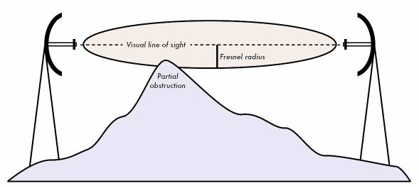
This is a straight-forward technique, which allows a user to ensure that the maximum bandwidth possible is achieved, at a certain distance. Increasing the height of the antenna allows the broadband wireless (radio) devices to clear obstacles that would otherwise have obstructed or scattered the signals, and possibly even achieve Line-of-Sight (LoS). However, there may be limits to the maximum height a user can specify for the antenna. The science in deciding the ideal height of the antenna is in the calculation of the Fresnel Zone. The Fresnel Zone can be visualised as a cigar-shaped ellipse between the transmitting and receiving points of a communication link (see below).
The calculations to working out the ideal antenna height from the Fresnel Zone can be picked up from the following site: http://www.vias.org/wirelessnetw/wndw_04_08b.html.
The point to keep in mind is that 60% of the Fresnel Zone should be kept clear of obstacles when finalizing the antenna height. Some vendors provide a distance commitment even under near-Line-of-Sight (nLoS) and No-Line-of-Sight (NLoS) conditions, in which case the 60% metric can be ignored.
Antenna type
Another technique to optimize the bandwidth/distance ratio is to use different types of antenna for different settings, if they are supported by the wireless broadband solution. A user may decide on an omni-directional antenna, or a planar/patch/panel antenna, or a grid/dish antenna, or a sector antenna, depending on the layout of the network and the obstacles involved.
Each type comes with its advantages and disadvantages.
| Type of Antenna | Pros | Cons | ||||||||||
| Omni-directional |
|
|
||||||||||
| Planar/Patch/Panel |
|
|
||||||||||
| Grid/Dish |
|
|
||||||||||
| Sector |
|
|
Topology
If a user reaches a dead-end when trying to adjust antenna height to ensure that the Fresnel Zone metric is adhered to, an alternative is to implement a different topology for the network. This allows a user to architect Line-of-Sight between communicating devices through an alternative route, if the same is not possible through the direct route. As briefly described in an earlier Tech. Brief write-up (referred earlier in the article), there are various architectures or topologies that can be applied in a wireless network.
The three popular topologies, for wireless networks, are Point-to-Point (PtP), Point-to-Multipoint (PtMP), and Mesh. In addition there is the Mixed topology, which is a combination of PtP or PtMP and Mesh. The user can evaluate different topologies, towards the objective of optimizing bandwidth and distance. Since choosing an appropriate topology is too big a topic to be covered in this note, all that a user needs to bear in mind is that, if LoS is a criterion for establishing communication, the wireless broadband vendor should support a variety of topologies.
Conclusion
Wireless broadband is a practical, albeit expensive, alternative to wired backhaul links. If the surveillance situation demands implementing a wireless broadband backhaul, users need not shy away from evaluating the same because of a lack of familiarity with the technology.
The thumb-rules when evaluating or implementing a wireless broadband solution, to ensure that the implementation is going to deliver on the bandwidth at a distance expectation, are that signal strength should be not less than 90% and that there should be no packet losses, when the link is tested.