
Cloud Radar Receiver and Up-Converter System
Overview
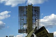
Millimeter wave cloud radars are radar systems designed to monitor and analyse cloud properties and read the precipitation level. They operate in frequencies between 24 and 110GHz (Ka and W bands). Cloud Radar analyses hydrometeors (various forms of precipitation) depending on the size and shape, classifies it and predicts the weather.
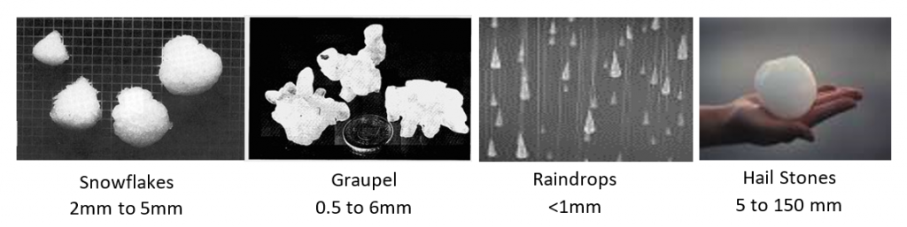
Cloud radar uses dual polarization transmission and receive method to determine hydrometeor shape. The Radar transmits electromagnetic waves of horizontal polarization and receives the scattered wave in both horizontal and vertical polarization components. Targeting with dual-polarization reveals the form of the droplet.
The Customer
The customer is a leading space research agency working in the field of telemetry, satellite tracking and command network among others.
The Requirement
The customer approached Mistral to design, develop, fabricate, test and qualify a Cloud Radar Receiver and Up-converter system. This was a built-to-spec project that consists of the following modules,
- OCXO
- PLDRO
- Local Oscillators
- Transmitter Receivers
- Controller and Power supply
- AC-DC Power supply
The requirement was to design a rugged chassis that encloses the Transmitter Up-convertor, two identical RF Receivers, LO Sources and Controller & DC Power Supply Card. The AC-DC Power Supply Unit was an external unit that has to be integrated with the chassis. The system had to undergo functional and ESS & QT tests, as per the ATP document approved by the customer.
Solution Provided
Mistral conducted a detailed requirement analysis to design and develop the Cloud Radar Receiver and upconverter. The study covered,
- Signal flow, architecture, and specifications of the complete sub-system
- Design approach
- Design of mechanical housing
- FPGA Firmware & software requirement for testing each module
- GUI Software requirements for the testing of all modules
- System Integration
- Quality and Environmental Qualification requirements
Design Approach
Mistral designed the Cloud Radar upconverter and downconverter by integrating RF-Line replaceable modules/cards inside a rugged chassis with proper mounting provisions, along with the interconnecting RF & power supply cables, and connectors.
The Cloud Radar Receiver & Upconverter Architecture
The architecture includes transmitter-receiver double heterodyne converters and power supply. The transmitter upconverter module up-converts the base band IF signal (120±30 MHz) to Ka-Band for transmission. Two identical receiver modules in the system down convert the incoming Ka-band receive signal to base band IF signal.
A high stability, low G-sensitivity OCXO [oven-controlled crystal oscillator] is used as a reference signal for S-Band LO and X-band LO sources. S-Band LO source uses Phase Lock Loop [PLL] and X Band LO source uses Phase Locked Dielectric Resonant Oscillator (PLDRO) for the respective LO frequency generation. These coherent LO signals are used for both up-conversion and down-conversion. 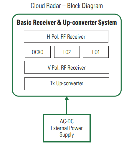
All the modules in the Radar system are controlled by the controller and power supply card. The DC Power supply required for various modules have been derived from the external AC-DC Power supply module, which takes AC power (230V ±10%, 50 Hz ± 2%) as input and generates +28V ripple free DC output. The Controller card built around Xilinx Artix-7 FPGA aids configuration and control of various RF modules through respective SPI, I2C and GPIOs. The Controller card also monitors the power supply status and the RF power status as per the check points in the design and displays the configuration and health status of the system in GUI via the Ethernet 10/100 interface.
Cloud Radar Features
- Polarimetric Pulsed Radar
- Transmitter upconverter (Upconverts input frequency of 120MHz to Ka band)
- Receiver Downconverter (Down-converts received Ka band signals to 120MHz)
- OCXO for reference signal for S-Band LO and X-band LO sources
- Controller and Power Supply Card based on Artix-7 XC7A100T FPGA
- RF Modules configuration through SPI, I2C and GPIO interfaces
- Transmitter Gain Control and output Power monitoring
- Dual channel Receivers Gain Control
- Ethernet PHY Transceiver with RJ45 connector
- Interfaces for power, System control, UART, JTAG, data bus and GPIO connections.
Software and GUI
Mistral developed FPGA Firmware for IO configuration and enabling monitoring and control of various modules in the Cloud Radar. A GUI, based on LabVIEW platform, was also developed to control the LO2 frequency and gain Tx and Rx chains. The configuration of RF synthesizer and RF up/down converters and adjusting the attenuator values are also done based on the data given through GUI. This application is interfaced with the system over LAN and supports,
- LO-2 frequency selection control
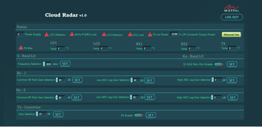
- Power supply status
- Transmitter Up-convertor output power status
- LO-1 / LO-2 output power status
- Digital control Attenuators
- Tuning and standalone testing of the whole system
Mistral also provided a custom developed ATP software to run functional tests on all deliverable units.
Quality and Environmental Qualification Tests
The Cloud Radar is designed to meet EMI/EMC standards as per MIL-STD-461-E. All interconnecting cables and connectors in the system are provided with appropriate shielding and grounding to ensure EMI/EMC protection and the mechanical enclosure is completely sealed with proper gaskets. The whole system is built using industrial grade components and the chassis is designed to meet IP65 protection standards. The product has undergone thorough electrical stress analysis and thermal analysis.
Cloud RADAR system was tested for following ESS standards,
- Vibration Tests for Sine Sweep in all three axes and Half Sine Shock [along each axis]
- IP65 Standards
- Humidity Test [Damp heat 40 C, 95% RH, 18hrs duration
Read the full case study to know more about design challenges and how these challenges were addressed.
