


Recent Trends on RF Data Converters
Overview
Analog to Digital Converters (ADC) and Digital to Analog Converters (DAC) act as a bridge between the Analog and Digital Domain. For years, these devices have remained the interface between analog and digital world. However, in higher Radio frequency (RF) range (Giga Hertz), the speed offered by ADC/DACs becomes a bottleneck.
The Traditional Approach – Heterodyne Conversion
Here’s a quick look into how an ADC/DAC is using in the traditional approach. An input RF signal is down converted to an Intermediate Frequency known as IF. The carrier wave is shifted to IF as an intermediate step by mixing the signal with a local oscillator. Once the signal is in IF range, simple analog circuits are used to filter, fine tune and amplify or attenuate the signal as required. Such processed analog signals are then taken to the digital world through ADC for digital signal processing.
Similarly, in Digital to Analog conversion, the processed signal data is taken from digital world to Analog world through DAC, and from IF to RF through UP Convertors. This approach is called Heterodyne Conversion (IF)
A typical Radio Receiver design based on Heterodyne Conversion (IF) is shown in Figure 1.
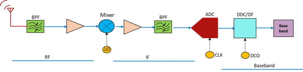
Figure 1
The modulated RF carrier is passed through a low-noise amplifier (LNA) and a band-pass filter (BPF) before converting to IF as shown in the Figure. After passing through anti-aliasing filter (AAF) the IF is digitized by ADC. Demodulation is carried out at baseband level.
The above approach is mostly due to the limitation of the conversion speed of ADCs. If we were to break the ADC speed barriers, would it be feasible to think of direct sampling?
Now, let’s look at the transmitter path for Heterodyne approach. Here, the baseband data is modulated in the digital domain & applied to DAC to convert to IF. The IF is upconverted to RF using a mixer & LO as shown in Figure 2.
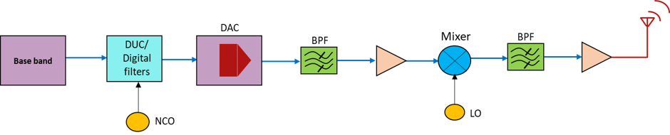
Figure 2
Direct Conversion or Zero IF
Direct Conversion or Zero IF is an alternate to Heterodyne (IF) approach of handling RF signals using High-speed RF ADCs. In this, the RF carrier is down-converted directly to baseband instead of IF. The RF carrier is converted to baseband (I&Q) using IQ mixer as shown in Figure 3. Two ADCs are used to digitize I&Q data. Here too, demodulation is carried out at baseband level.
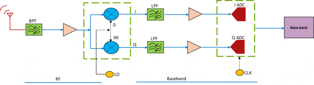
Figure 3
RF ADC
New high-frequency ADCs known as RF ADCs can directly sample wideband signals beyond 6.0GHz. In addition, these RF ADCs have built-in signal processing capabilities. An RF system designer, using the latest RF ADC, needs to design only the hardware platform and use software to configure the hardware to suit the application. An RF ADC with signal processing capabilities is shown in Figure 4.
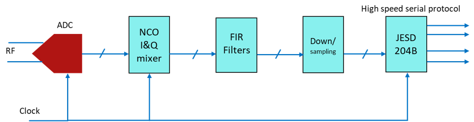
Figure 4
Now, let’s look at the transmitter path. The baseband data is modulated in I&Q modulator and applied to two DACs, which is further upconverted to RF using IQ mixer and LO as shown in Figure 5.
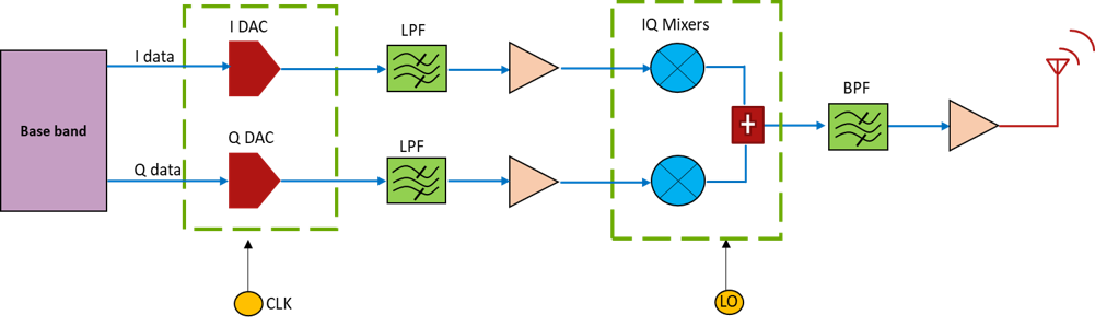
Figure 5
RF DAC
The high frequency DAC, known as RF DAC, can generate frequency up to 6GHz directly, thereby eliminating the need for IF to RF conversion. RF DAC includes signal processing as shown in Figure 6.
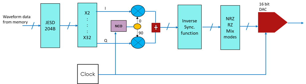
Figure 6
Conclusion
Zero IF systems reduce component count and complexity of the design and bring in a lot of advantages. The System Noise Factor is minimised, and the out-band RF blockers can be attenuated by the RF front-end filters. Overall Zero IF systems are compact and provide better performance. At the same time, since High-speed ADCs are new in the market and expensive, a cautious approach is required before finalising the design.
The trends for Zero IF systems are further moving towards System on Chip concept. High-speed ADCs and DACs integrated with programmable logic eliminate the need for complex digital interfaces between converters and digital circuit. Such devices can be placed with the antennas and digitally interfaced to the processing world.